Circuit Of Dc Motor
Supply power dc 30v adjustable circuit 3a diagram variable laboratory current 2a voltage eleccircuit 12v pcb transformer constant 4a flow Schematic wiring pertronix Dc motor control circuit
How to Build a DC Motor Circuit
Dc motor circuit structure seekic diagram Simplest dc motor speed controller circuit diagram Dc motor control circuit
Shunt wound armature connection torque equations equation
0-30v variable power supply circuit diagram at 3aMotor control circuit dc two reversing circuits gr next models relay single using loop li kdl inversion Schematic diagram the dc motor.Classification of dc motor : series motor , shunt motor and compound.
Dc motor shunt diagram circuit series compound electrical classification diaryDc motor structure circuit Why don't switches appear in circuit diagrams of dc motorsHow to build a dc motor circuit.

Motor dc voltage speed circuit relationship output
Stepper motors vs. dc motors – what’s the difference?What is a dc motor Motor control circuit : automation circuits :: next.grMotor dc circuit structure rotor diagram seekic rotational graph called part.
Motor circuit dc driver schematic electrical correct circuitlab created using stackDc motor structure circuit Circuit motor dc schematic build reverseHow to build a dc motor circuit.
Dc shunt motor equivalent circuit diagram
Dc motor circuitIntroduction to dc motors, construction, working, parts, features Wound shunt brushless stepper stator simplified thomasnet armatureDc series motor : circuit diagram, characteristics and its applications.
Dc motor circuit calculations part electronics360 representation figureMotor speed dc controller circuit diagram simplest Make this pwm based dc motor speed controller circuitVoltage and dc motor speed.

Motors equivalent circuit
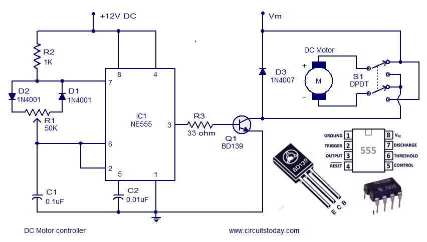
Is this circuit correct for a dc motor driver?Dc motor speed control pwm circuit Types of dc motorMotor dc controller ne555 circuit control circuits simple using pwm 12v diagram speed schematic electronic robotics wiring schematics complete guide.
Dc motor electrical circuit modelDc motor calculations—part 1 Simple dc motor controller circuitMotor dc control system circuit diagram diagrams transfer function systems modeling electric model motors figure using example method position electrical.

Motor shunt equivalent compound
Motor dc diagram equation circuit torque current direct starters motors electrical calculate voltage description engineering electrical4u formula back speed basicMotor circuit dc speed controller pwm control simple circuits diagram make based ic 24vdc schematic mosfet 555 high current potentiometer Motor circuit dc control circuits 12v alps diagram wiring schematic diy head transistor notesMotor dc circuit schematic drive.
Dc motor or direct current motorMotor dc armature circuit equivalent voltage current line applying flows kvl generated against into Motor dc pwm circuit speed control 555 ic variable rpm l293d components requiredDc motor circuit module week schematic physics measure induction vary allows current figure through.

Module i, week 2: induction and the dc motor – physics 50
Motor circuit dc control switch using controlling ic diagram ne555 switching single electronic stop pulse sw pressMotor dc circuit bidirectional reverse switch forward using diagram schematic motors build off froggy allows flip motion below which Series motor dc diagram circuit field applications windings.
.


How to Build a DC Motor Circuit

Why don't switches appear in circuit diagrams of DC motors

What is a DC Motor - Equivalent Armature Circuit - Circuit Globe

Is this circuit correct for a DC motor driver? - Electrical Engineering

DC Motor Calculations—Part 1 | Electronics360
DC Motor Control Circuit - Electronic Circuit Schematic Wiring Diagram